

Progressing Forwards
At the end of the previous post I had processed the Openstreet map data – created polygon data for each building and then drawn these buildings using the GL_LINE primitives to give us a wireframe outline for the building as shown below:
To take this to the next stage – the next task was to draw solid walls. We already have the corners of each of the walls so we just have to convert this to a list of triangles and submit this list to OpenGL. The naive way to draw all of the buildings would be to create the triangles per building and then submit these as a single draw call. However, this approach would be very inefficient due to the overhead associated with making so many draw calls.
Primitive types
The better way to submit the vertices for drawing would be to batch the vertices into a single buffer as this allows you to then draw multiple objects(buildings) in a single draw call. I chose to draw the walls using GL_TRIANGLE_STRIP. One has the advantage over GL_TRIANGLE is that you can save a lot of memory as you only have to store one vertex per triangle, instead of having to use three. This is also the recommended primitive type to use on iOS platforms so it seemed like a good place to start. However, using GL_TRIANGLE still probably would have been OK as long as we batched the vertex data to limit draw calls.
The importance of batching
As for how to batch calls when each vertex you add to your vertex array creates another triangle – the solution is to insert “degenerate triangles”. Degenerate triangles are triangles with an area of 0. In our case we should insert a degenerate triangle between each of our separate buildings to connect them together. You can imagine between the last vertex between building n and the first vertex of building n+1 there is an invisible triangle connecting them. The graphics hardware is clever enough to recognise the degenerate triangle so rendering these does not lead to a loss in performance. The simplest way to insert a degenerate triangle is to simply duplicate the first and last vertex of every object you need to connect.
Results and Issues
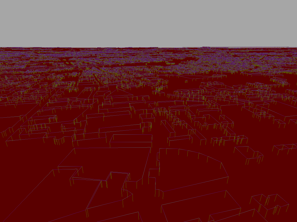
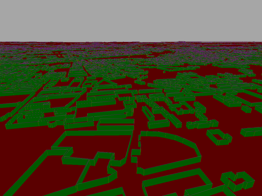
The images below shows the final result of drawing the building walls. The first image shows the scene with culling disabled. The second image shows the scene with backface culling enabled. backface culling is useful as when the roof’s are implemented only the walls closest to the camera will be visible – the back faces/walls will be hidden by the opaque roof’s. By not drawing these hidden faces we prevent the hardware from having to process these pixels thus saving filtrate. However as the screen shot shows – when the backface culling is enabled some of the front faces disappear. The hardware determines which face is the “back”(or front) face by the winding of the triangles – this will require some further investigation to solve. The issue is likely that the OSM buildings are not all defined in the same order (clockwise/anticlockwise) or my code that generates the triangle strips code simply has some bugs!
A point worth noting: OpenGLES 3.0 allows you to use the “primitive restart” functionality to batch draw calls – however I have not yet had a change to experiment with OpengGLES 3.0 API so I have no idea how this compares to using degenerate triangles. It would save a bit of memory as you would no longer have to submit duplicate vertices (or as many duplicate indices).

1 thought on “Rendering solid walls”